What Is GPR?

Ground Penetrating Radar Technology Explained
This page is designed as a basic introduction to some of the key concepts of ground penetrating radar. Ground penetrating radar is also known as GPR, Georadar, and ground probing radar.
A GPR system is made up of three main components:
- Control unit
- Antenna
- Power Supply
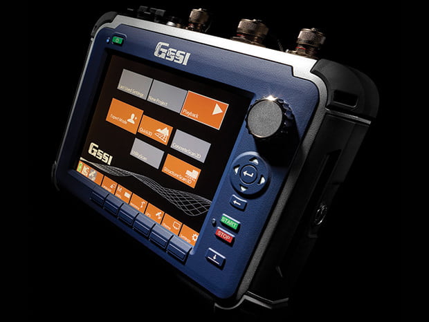
GSSI GPR equipment can be run with a variety of power supplies ranging from small rechargeable batteries to vehicle batteries and normal 110/220-volt. Connectors and adapters are available for each power source type. The unit in the photo above can run from a small internal rechargeable battery or external power.

GPR Control Unit and Antenna
The control unit contains the electronics which trigger the pulse of radar energy that the antenna sends into the ground. It also has a built-in computer and hard disk/solid state memory to store data for examination after fieldwork. Some systems, such as the GSSI SIR 30, are controlled by an attached Windows laptop computer with pre-loaded control software. This system allows data processing and interpretation without having to download radar files into another computer.
The antenna receives the electrical pulse produced by the control unit, amplifies it and transmits it into the ground or other medium at a particular frequency. Antenna frequency is one major factor in depth penetration. The higher the frequency of the antenna, the shallower into the ground it will penetrate. A higher frequency antenna will also ‘see’ smaller targets. Antenna choice is one of the most important factors in survey design. The following table shows antenna frequency, approximate depth penetration and appropriate application.
| Appropriate Application | Primary Antenna Choice | Secondary Antenna Choice | Approximate Depth Range |
|---|---|---|---|
| Structural Concrete, Roadways, Bridge Decks | 2600 MHz | 1600 MHz | 0-0.3 m (0-1.0 ft) |
| Structural Concrete, Roadways, Bridge Decks | 1600 MHz | 1000 MHz | 0-0.45 m (0-1.5 ft) |
| Structural Concrete, Roadways, Bridge Decks | 1000 MHz | 900 MHz | 0-0.6 m (0-2.0 ft) |
| Concrete, Shallow Soils, Archaeology | 900 MHz | 400 MHz | 0-1 m (0-3 ft) |
| Shallow Geology, Utilities, USTs, Archaeology | 400 MHz | 270 MHz | 0-4 m (0-12 ft) |
| Geology, Environmental, Utility, Archaeology | 270 MHz | 200 MHz | 0-5.5 m (0-18 ft) |
| Geology, Environmental, Utility, Archaeology | 200 MHz | 100 MHz | 0-9 m (0-30 ft) |
| Geologic Profiling | 100 MHz | MLF (16-80 MHz) | 0-30 m (0-90 ft) |
| Geologic Profiling | MLF (16-80 MHz) | None | Greater than 30 m (90 ft) |

GPR Method
GPR works by sending a tiny pulse of energy into a material and recording the strength and the time required for the return of any reflected signal. A series of pulses over a single area make up what is called a scan. Reflections are produced whenever the energy pulse enters into a material with different electrical conduction properties or dielectric permittivity from the material it left. The strength, or amplitude, of the reflection is determined by the contrast in the dielectric constants and conductivities of the two materials. This means that a pulse which moves from dry sand (dielectric of 5) to wet sand (dielectric of 30) will produce a very strong reflection, while moving from dry sand (5) to limestone (7) will produce a relatively weak reflection.
While some of the GPR energy pulse is reflected back to the antenna, energy also keeps traveling through the material until it either dissipates (attenuates) or the GPR control unit has closed its time window. The rate of signal attenuation varies widely and is dependent on the properties of the material through which the pulse is passing.

GPR Method (Continued)
Materials with a high dielectric will slow the radar wave and it will not be able to penetrate as far. Materials with high conductivity will attenuate the signal rapidly. Water saturation dramatically raises the dielectric of a material, so a survey area should be carefully inspected for signs of water penetration.
Metals are considered to be a complete reflector and do not allow any amount of signal to pass through. Materials beneath a metal sheet, fine metal mesh, or pan decking will not be visible.
Radar energy is not emitted from the antenna in a straight line. It is emitted in a cone shape (picture on left). The two-way travel time for energy at the leading edge of the cone is longer than for energy directly beneath the antenna. This is because that leading edge of the cone represents the hypotenuse of a right triangle.
Since it takes longer for that energy to be received, it is recorded farther down in the profile. As the antenna is moved over a target, the distance between the two decreases until the antenna is over the target and increases as the antenna is moved away. It is for this reason that a single target will appear in the data as a hyperbola, or inverted “U.” The target is actually at the peak amplitude of the positive wavelet.

Data Processing
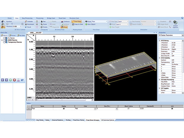
Data is collected in parallel transects and then placed together in the appropriate locations for computer processing in a specialized software program such as GSSI’s RADAN. The computer then produces a horizontal surface at a particular depth in the record. This is referred to as a depth slice, which allows operators to interpret a planview of the survey area.
In many situations, a GPR operator will simply note the location of a target so that it can be avoided. For these clients, it may only be necessary to use a simple linescan format in order to mark the approximate area of the target on the survey surface. Other clients may require detailed subsurface maps and depth to features.
These situations will require the operator to use GSSI GPR processing software, which applies mathematical functions to the data in order to remove background interference, migrate hyperbolas, calculate accurate depth and much more.
For more information on GPR, please see our FAQ page or Contact GSSI.
